ECAD PLM integration works best when change stays out of PLM (until it's ready)
Most ECAD PLM integration projects focus on moving bills of materials (BOMs) and release files faster. The harder problem is deciding which changes should reach PLM at all. This guide explains a two-layer model that keeps daily design change out of PLM until it's approved, then walks through setup step by step.
Key takeaways
- ECAD PLM integration connects electronics design tools to a product lifecycle management (PLM) system so BOMs and release files reach PLM without manual re-entry.
- Design change and product change are different. Engineers make many small edits on every board, while PLM is built to track fewer, formal changes to released products.
- A review and revision control layer in front of PLM lets teams compare schematic and BOM changes visually and approve them before any push.
- Integration should run in both directions: released BOMs go to PLM, and part lifecycle and approved-part data come back to the design team.
Introduction
Many hardware companies treat ECAD PLM integration as a plumbing job. Connect the design tool to PLM and map a few fields, and the data should flow. The failures show up later, when the integration pushes a state of the design that nobody approved.
PLM systems grew up around mechanical parts and formal change records, where each change is large and deliberate. Electronics design moves in small, fast steps, and most of those steps should never become a formal record.
The pressure on that handoff keeps growing. According to Z2Data's analysis, published as the Z2Data 2025 obsolescence analysis, "In 2025, over 620,000 electronic parts were discontinued by manufacturers."
The same analysis found that 52% of 2025 end-of-life (EOL) events never came through a manufacturer product change notification (PCN). Each discontinued part on a live board forces a design change, and that change has to land in PLM correctly.
What is ECAD PLM integration?
ECAD PLM integration is the data link between electronics design tools and a product lifecycle management system. It sends released BOMs and design files into PLM, and it brings approved part data back to the people designing the board.
ECAD stands for electronic computer-aided design. It covers schematic capture and PCB layout, which together produce the BOM. PLM is the company's system of record for parts, BOMs, change orders, and compliance data, in tools such as Windchill or Teamcenter.
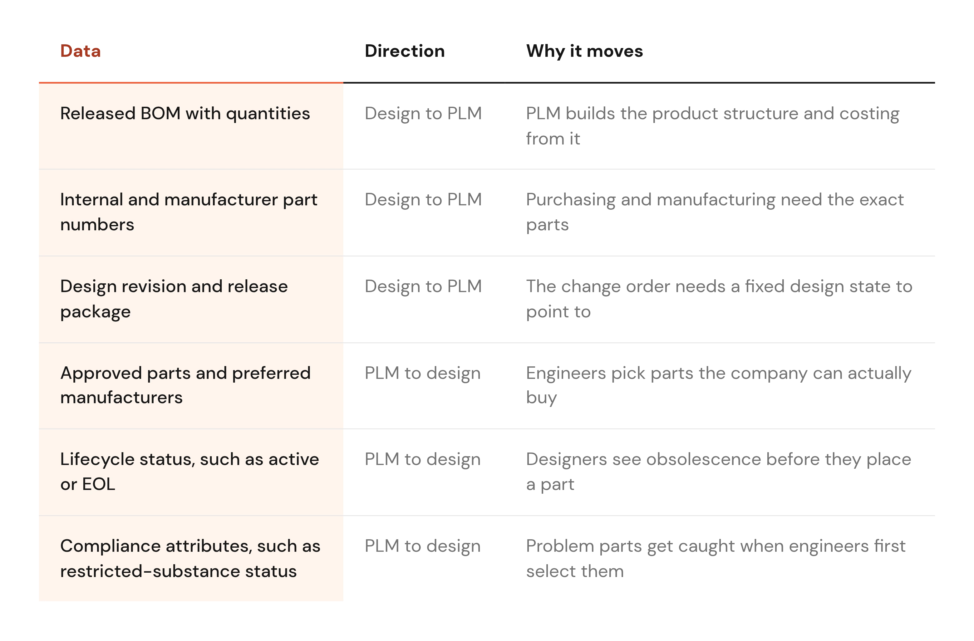
Without the link, someone exports a spreadsheet from the design tool and re-keys it into PLM. Every manual copy is a chance for a part number or quantity to drift from what's on the board. Here is what typically moves in each direction. At mid-size and large manufacturers, that PLM integration often has to serve more than one ECAD tool, a problem covered in the sections below.
The two-layer model: design change vs. product change
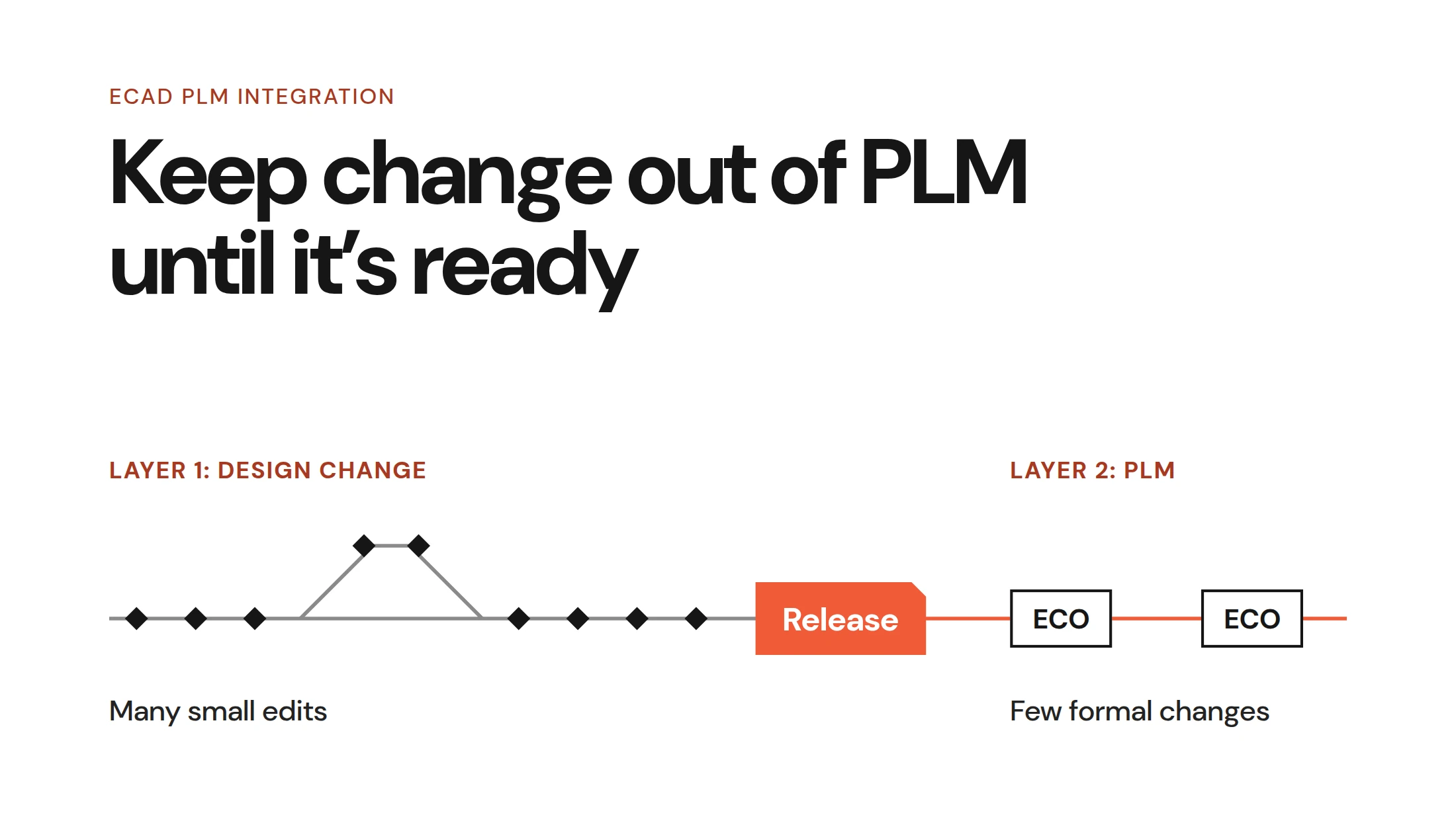
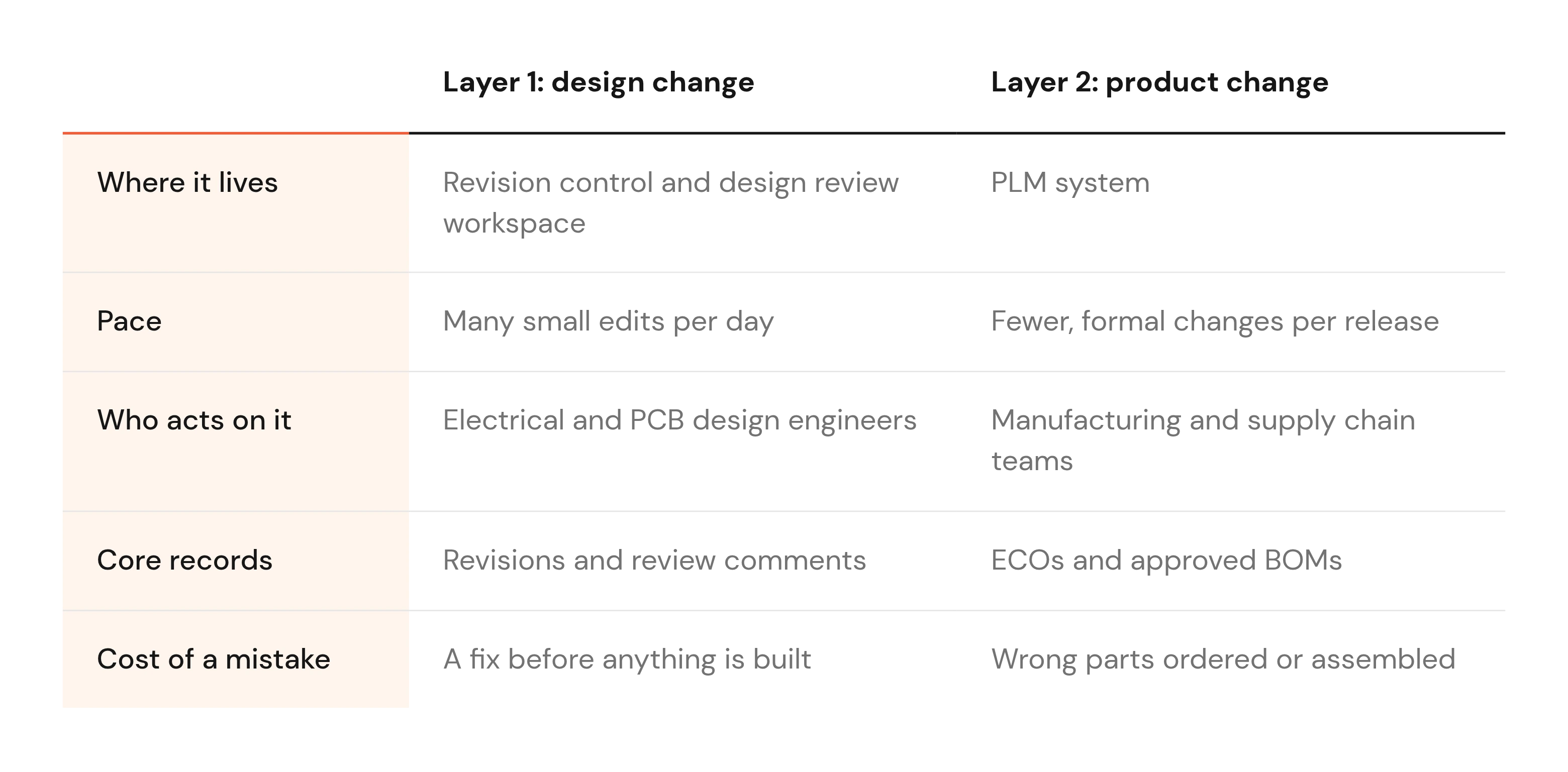
Good ECAD change management starts by admitting there are two kinds of change. The first is design change: the work-in-progress edits engineers make while a board is still taking shape. The second is product change: the formal, released changes that manufacturing and supply chain teams act on in PLM.
Each layer needs its own system and its own rules. The handoff between them is the release, and that handoff decides whether an integration keeps PLM accurate or fills it with noise.
Layer 1: work-in-progress design change
Design change is fast and granular. An engineer swaps a capacitor, reroutes a net, tries a different regulator on a branch, and opens a design review before merging it back. On a complex board, those edits pile up every day.
This layer needs ECAD change management with full version history and visual diffs of schematics, layouts, and BOMs. A good diff also shows attribute-level changes, such as a swapped part number on a resistor whose symbol looks identical.
Folder copies break this layer. When revisions live in files named "rev_C_final_v2," nobody can say what changed between them, which is the core problem with versioning in hardware design. One hardware engineer told us that someone on the team still writes down by hand when a resistor changes value.
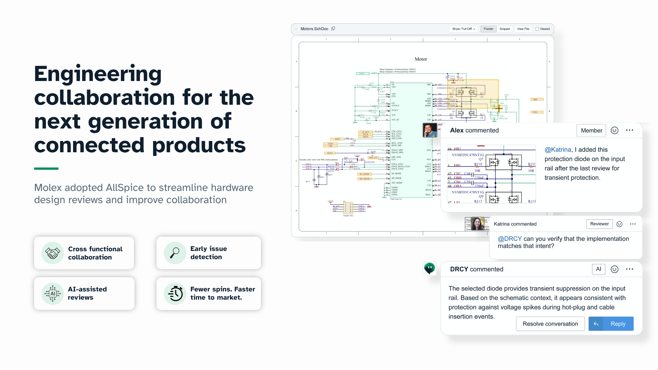
Review comments belong here too, pinned to the exact net or part in question. None of this activity belongs in PLM, which was never designed to hold it.
Layer 2: released product change in PLM
Product change is slower and formal. It runs through engineering change requests (ECRs) and engineering change orders (ECOs), the documents that propose and approve a change to a released product. PLM also holds the approved BOM, part lifecycle status, supplier data, and compliance records.
PLM is good at this work, but it is poor at showing an engineer what changed on a schematic. Another engineer put it bluntly on a call with us: "I hate PLM. All engineers and CAD members hate PLM."
That frustration usually comes from asking PLM to do layer 1 work. Compliance is where PLM earns its place, because restricted-substance data has to travel with every part record. According to the TÜV SÜD REACH update, the Candidate List under the EU's REACH chemicals regulation "now stands at 253" substances.
A new listing can change a production part's status, and an ECO in PLM is the right way to act on it. Side by side, the two layers look like this.
The release: where the two layers meet
A release is a reviewed, tagged design revision plus the outputs built from it, including the BOM and fabrication files. It is the only event that should trigger a push to PLM.
This rule gives everyone a clean reference point, because each ECO can point at one release and its review history. For naming and packaging conventions, see our guide to structuring hardware releases.
Multi-board products raise the stakes, because each board is a separate printed circuit board assembly (PCBA). Every PCBA revision has to line up with the product release in PLM. Our post on managing projects with multiple PCBAs covers how to keep those revisions aligned.
Where ECAD PLM integrations break
Most integrations work fine when every step goes as planned. The failures cluster at the handoff, where design data crosses from layer 1 to layer 2 without the right checks.
Unreviewed changes reach PLM
The most common break is timing. A BOM gets exported mid-change and attached to an ECO while the board keeps moving, so the change order describes a design that never existed.
The cost shows up at the factory. One customer told us the outcome they fear most is having their team overseas during first board bring-up, fighting BOM issues instead of testing hardware. In our view, much of the rework blamed on poor integration starts with a push that should have waited for review.
Respins make this a routine risk. The PCD&F 2025 designer survey found: "Nearly 60% produce just 1–5 respins a year, and 81% say that hasn't increased in the past 12 to 18 months." Each respin is another revision that has to reach PLM with a matching BOM.
Part data drifts between the library and PLM
The second break is slow drift. The ECAD part library says one thing about a part, and PLM says another. It might be a different internal part number, or an approved manufacturer that was removed months ago.
One-way sync makes drift worse. If data only flows from design to PLM, lifecycle updates recorded in PLM never reach the engineer choosing parts. Since so many EOL events arrive without a PCN, the PLM part record may be the first place a status change gets logged.
The fix is two-way sync for the fields PLM owns, so designers see lifecycle and approval status before a part lands on a schematic.
One integration per ECAD tool
Large manufacturers rarely run a single ECAD tool. Acquisitions bring in teams on Altium Designer, Cadence, OrCAD, and KiCad. Native connectors usually come from one ECAD vendor and cover only that vendor's files.
The result is a patchwork. One product line has a working PLM link while another still exports spreadsheets, so nobody can compare a change across both. An ECAD-agnostic revision control layer built for hardware fixes this by giving every tool the same review and release path into PLM.
How to set up ECAD PLM integration, step by step
The steps below put the two-layer model into practice. They start with what PLM needs and work backward to the checks that protect it.
1. Define what PLM needs from a release
Start with the receiving end: work with the PLM administrator to list every field a release must carry. Typical items include internal part number, revision, BOM columns, manufacturer part numbers, compliance attributes, and output files.
Do this before layout is finished, since fields added late tend to get filled in by hand. Write the list down as a release specification that every board follows.
2. Map part and BOM fields between ECAD and PLM
Next, pick one primary key that links a part in the ECAD library to its PLM record. For most manufacturers, that's the internal part number, because manufacturer part numbers can change or have alternates.
Then map every attribute. The ECAD "Value" field might map to a PLM description, and a library manufacturer part number field to the approved part in PLM. For each field, assign one owner and one sync direction.
Design owns structure, meaning which parts appear and in what quantity. PLM owns status, such as lifecycle and approval, because two systems editing the same field will eventually disagree.
3. Put a design review in front of every release
This step is the gate between the two layers. Before anything is tagged as a release, reviewers compare the new revision to the last one with visual diffs of the schematic and BOM.
A hardware design review checklist gives reviewers the same questions for every board, such as power sequencing and connector pinouts.
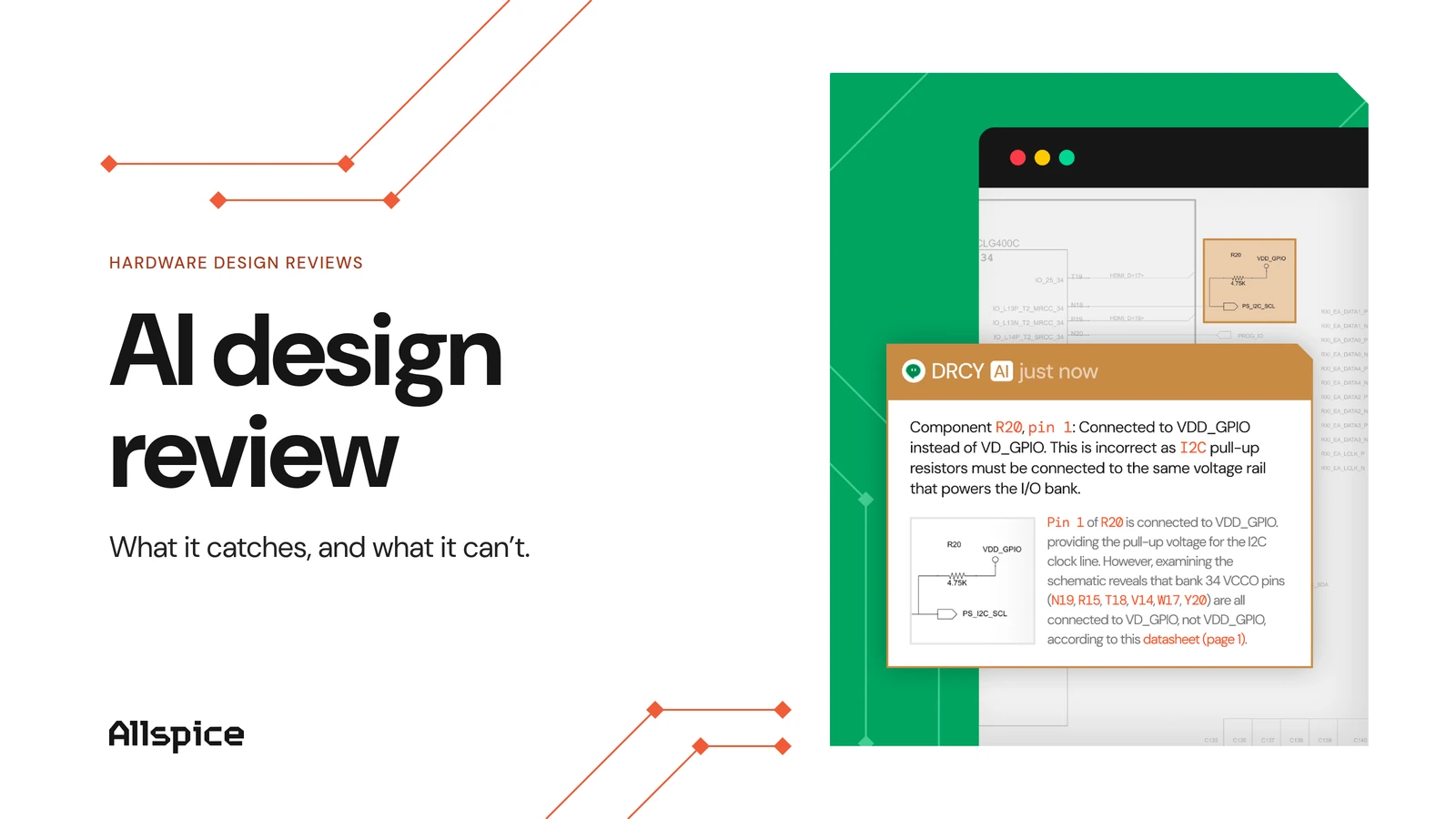
AI can take a first pass on schematics before people do. AI-assisted schematic review with DRCY cross-references schematic components against their datasheets and flags potential issues. The engineer reviews each finding and makes the call.
4. Automate BOM validation before the push
Some checks are too repetitive for people to do well. Automated checks can run on every release candidate, much like CI/CD pipelines test software. Common BOM checks include:
- Every line has an internal part number that exists in PLM.
- No part carries an EOL or not-recommended-for-new-designs status.
- No reference designator, the label such as R12 or C4, appears twice.
- Every part carries the compliance attributes the release specification requires.
Set failures to block the release so it never reaches PLM. AllSpice runs these as automated BOM and design checks on each design revision.
5. Push released BOMs to PLM and pull part status back
With review and validation in place, the push becomes routine. An approved release sends its BOM and release package to PLM, and the new ECO references that release by its tag.
The return path matters just as much. Lifecycle and compliance changes recorded in PLM should flow back to the design workspace, so engineers see them on the next revision.
The AllSpice hardware design review platform offers bidirectional PLM and enterprise resource planning (ERP) sync through its REST API, including Siemens and Oracle systems. AllSpice sits in front of PLM as the review and revision layer.
Good integration keeps PLM clean and engineers in their design tools
ECAD PLM integration fails when PLM receives designs nobody approved, and it works when only reviewed, versioned releases reach it. Keeping the two layers separate lets each system do the job it was built for.
There are caveats. Field mapping takes real effort and agreement between engineering and operations. PLM remains the system of record for released product data, so the design layer feeds PLM and never replaces it.
If you're starting fresh, start with the BOM. Get one board's BOM through review and a clean push, then add part status on the return path. As obsolescence and compliance lists keep growing, that clean handoff will carry more weight with every release.
FAQs
What is the difference between ECAD and PLM?
ECAD tools are where engineers draw schematics and lay out PCBs, which produce the BOM for each board. PLM is the system of record for released parts, BOMs, change orders, and compliance data across the whole product.
Should every design change create an ECO in PLM?
No, daily design edits belong in a versioned design review workspace where engineers can compare and approve them. An ECO in PLM should open only when a reviewed revision is tagged as a release that manufacturing will build.
What data should sync from PLM back to ECAD?
Part lifecycle status and compliance attributes should flow back from PLM, along with the approved manufacturers for each part. That way engineers see EOL parts and restricted substances before they place a part on a schematic.