Models are getting better by the day. As raw AI capability becomes table stakes, the biggest differentiator in results is shifting from which model you use to what data you feed it. In hardware engineering, where data quality varies more than in other fields, this distinction matters.
Hardware teams live in 2D schematics, 3D models, binary design files, and PDFs. Most of that data was optimized for human eyes, not machine consumption. LLMs, like all computer programs, operate best on text: structured, semantic, traversable text. Most hardware data is none of those things.
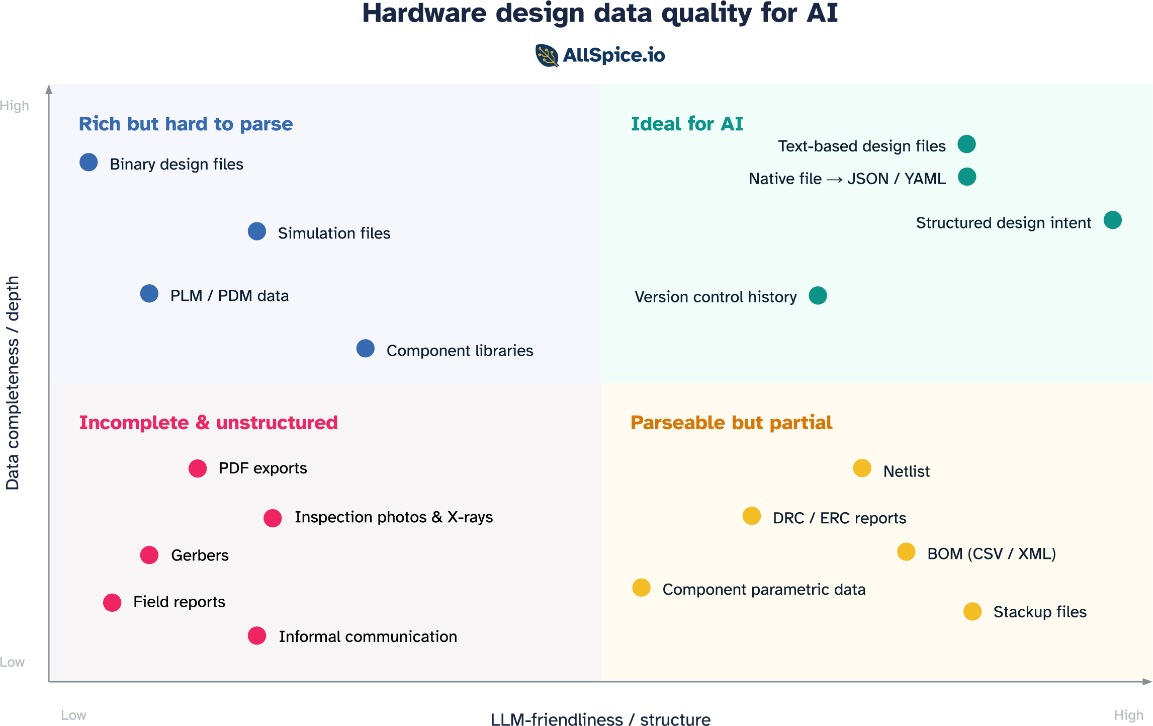
When thinking about how useful a data source is for an AI agent, two axes define the space:
- Depth: how complete a picture does the data paint? Does it capture full design intent, or just a slice of it?
- Structure: how parseable, organized, and understandable is the data to an LLM?
Plot the data sources hardware engineers rely on daily across those two axes and four distinct categories emerge.
Incomplete & unstructured
A large part of an engineer's day-to-day life lives in this quadrant. It is also where AI workflows go to struggle.
PDFs and rendered exports
Though they look complete to the human eye, rendered exports discard the underlying data model the moment they're created. Net names exist as pixels, not strings. Component references are visual annotations, not database links. An LLM reading a schematic PDF has no access to the underlying structure of the content. This is where most hallucinations originate. Based on our benchmark testing, 70-80% of LLM hallucinations when handling hardware designs are caused by PDFs and images.
Gerbers
Designed to drive photoplotters in the 1980s, Gerbers contain copper geometry and nothing else. No component identities, no net names, no signal types, no design intent. They were built for a specific machine and serve that purpose well. For an LLM trying to reason about a circuit, they're nearly useless.
Inspection images
AOI images, X-ray scans, and microscope photos contain real information about the physical state of a board. But they're unstructured images with no link back to the design database. Without that context, an LLM can describe what it sees but can't tell you which component it's looking at or whether what it sees is within spec.
Field failure reports
Real-world evidence of design weaknesses, written in inconsistent language with no component references or schematic cross-links. Extremely valuable signal, almost completely inaccessible to an LLM without significant preprocessing.
Informal communication
This one doesn't look like a format at all, but it's arguably where the most valuable design knowledge lives. Email threads, Slack messages, whiteboard sessions, factory-floor conversations. None of it is structured, very little is retrievable, and it evaporates when engineers leave the team. For an LLM trying to understand why a design is the way it is, this is the biggest gap.
These formats were built for a specific consumer: a human eye or a specific machine. General machine-readability was never the requirement.
Parseable but partial
Because most native design files are binary blobs that only the tools that created them can read, a set of structured export formats has emerged to serve as the interface with the outside world. These formats are LLM-friendly in structure, but each captures only a slice of the design.
Netlist
The most fundamental structured output of a schematic: a list of components and the nets connecting their pins. Clean, text-based, and directly traversable by an LLM. What's missing is placement, constraints, and intent.
BOM (CSV / XML)
The parts list: what components are in the design, how many, and with manufacturer part numbers that link to real-world datasheets. Highly structured and useful for component-level questions like availability, cost, and substitution. What it cannot do is reason about the circuit. A BOM is the ingredient list without the recipe.
DRC and ERC reports
Structured lists of design rule violations: locations, rule references, severity levels. An LLM can parse them directly and reason about which violations matter and what the likely consequences are. The limitation is context. A report tells you that a rule was violated, but not why those traces are there, what signals they carry, or whether the violation is in a critical area or a benign one. It captures what the tool flagged, not what an experienced engineer would focus on.
Stackup files
Layer count, dielectric materials, copper weights, and impedance targets. Fully structured and useful for questions about controlled impedance and manufacturability. But it covers only the physical layer construction, with no circuit context. Knowing the stackup without knowing what's being routed on it is only half the answer.
Component parametric data
Structured specifications from component APIs: ratings, package information, pricing, availability, lifecycle status. An LLM can answer useful questions about a part in isolation. What it cannot answer is how that part is being used in this specific design, whether it's operating within its ratings, or whether it was the right choice for the application.
Each of these formats was optimized to communicate one thing to one consumer. The netlist for the layout tool. The BOM for procurement. The DRC report for the reviewer. The stackup for the fab. That single-purpose design is also their limitation. The most important questions in hardware — is this design correct, what is likely to fail, what should we change — require synthesizing across all of them at once, plus the native design context that none of them expose.
Rich but hard to parse
This is where most native design files live today. The data is all there, but locked behind binary formats and tools that require specialist knowledge to operate. Getting it into a form an LLM can use takes real engineering effort.
Binary design files
Native ECAD files, such as Cadence OrCAD .dsn, Allegro .brd, System Capture .sdax, Altium .SchDoc, and Siemens Xpedition .pcbx, contain everything a designer knows about a board: every net, every component parameter, every constraint, every hierarchical relationship. For most engineers, they are the source of truth.
The problem is that these formats were never designed to be read by anything other than the tool that created them. They were built in an era when a file was simply a way to persist state between sessions, a save format and not a data exchange medium. That was a reasonable assumption when the only consumer was a designer at a workstation. But boards don't come to life through one engineer and one tool. They involve mechanical teams, firmware engineers, procurement, and manufacturing, and that closed assumption forces everyone else to work from exports: PDFs that lose all connectivity and structure, or partial formats like netlists and BOMs that capture only a slice of the design.
LLMs make this tension even more acute. A language model doesn't open files, it reads text. The mismatch is a collision between formats designed for single-application workflows and a technology that needs data to flow freely.
PLM and PDM systems
Product lifecycle and product data management systems, such as Arena, Windchill, and Teamcenter, hold some of the richest design data in the organization: final BOMs, revision history, approved vendor lists, change orders with rationale. This data is structured inside the tool, but it was designed to serve a specific workflow, not to be consumed externally. Export formats vary widely between systems and versions, and getting clean, semantically intact data out for LLM consumption is a substantial engineering project.
Component library files
Schematic symbols, PCB footprints, and 3D models in component libraries are a rich knowledge source: pin types, electrical properties, recommended land patterns, thermal data. This data is stored in tool-specific formats that vary enormously and are not designed for external consumption. The component library is often the most carefully maintained data asset a hardware team has, and it is almost entirely inaccessible to an LLM without a purpose-built extraction layer.
Simulation files
SPICE netlists with extracted parasitics, HyperLynx .hyp files, and Ansys SIwave projects are information-dense in a way most other formats are not. They encode not just the design but its physical behavior: impedances, propagation delays, thermal distributions. A simulation file for a complex power delivery network contains more information about how the board actually works than the schematic does. But the formats are tool-specific, often binary, and require deep domain knowledge to interpret even when readable. Even a SPICE file, which is technically text, becomes impractical for an LLM to reason over without significant preprocessing once parasitics are extracted at scale.
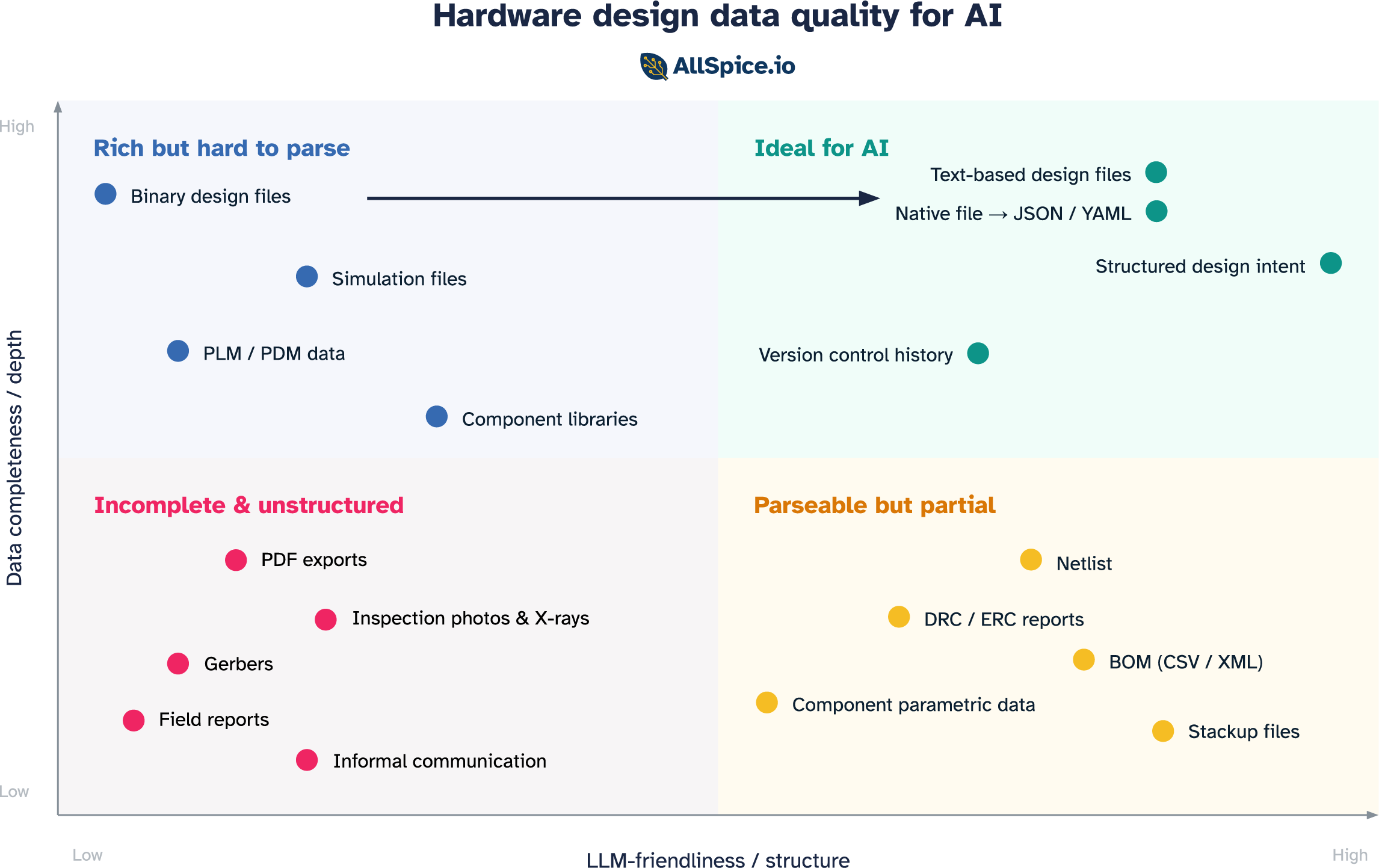
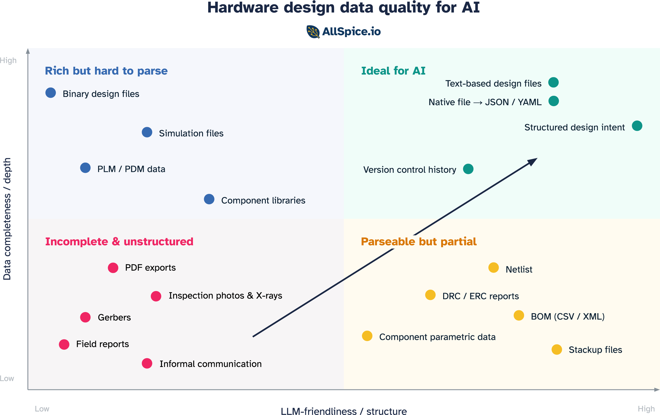
Moving your team to the top right
Knowing where your data sits is the first step. Moving it is the second. The good news is that this doesn't require replacing your tools or rebuilding your workflows from scratch. It requires three shifts, roughly in order of difficulty.
1. Invest in version control as data infrastructure
The first shift is treating version control the way software teams do, meaning not as a backup system, but as the authoritative record of how a design evolved and why. Most hardware teams still manage design files the way documents were managed in the 1990s. Folders on a shared drive, file names like board_v3_FINAL_revised2.sch, no history, no attribution.
Good version control solves problems that go beyond AI. It removes the reliance on individual engineers naming files correctly and putting them in the right place. It creates a structured, searchable record of every change. It makes collaboration tractable across a team. And for an LLM, it transforms the design from a static snapshot into a living history. In this scenario, every entry becomes a timestamped, attributed record of what changed and, if the team writes meaningful messages, why.
Git is the natural choice here. It is what software teams use, it is what modern tooling is built around, and it is the foundation that the rest of this infrastructure builds on. The prerequisite is that design files are text-based enough to track changes meaningfully. Binary files can be version-controlled, but the history is nearly useless. You know something changed, not what. Which brings us to the next shift.

2. Get your design data into a readable form
The next step is making sure the files you are versioning are actually understandable to a model.
The most straightforward path is format. Moving design data into structured, text-based representations is the most straightforward path. Text is what LLMs are built for. The moment a schematic is a structured text file rather than a binary blob, the model can read it and reason over it directly. Some tools already store design files this way natively. For teams on proprietary tools, the equivalent is building export pipelines that convert native files into structured representations that preserve component identity, net relationships, and hierarchy.
Beyond format is live access. Tools that expose APIs or MCP integrations allow a model to query design data directly rather than reasoning from a static export. Instead of uploading a file and asking questions about a snapshot, the model can ask the tool in real time. The hardware tooling ecosystem is beginning to support this.
3. Capture intent in a structured way
This is the hardest shift, and arguably the most impactful one. The first two are primarily technical, changing how data is stored and accessed. This one requires changing how engineers work.
Every experienced hardware engineer carries a body of knowledge that never makes it into any file. It’s things like why this topology was chosen over the alternatives, which constraints are hard requirements and which are conservative rules of thumb, or what was tried in the last revision and why it was changed. This is the reasoning layer, and it’s what separates a senior engineer evaluating a design from a junior one checking it against a rule list.
When that knowledge lives only in someone's head, it's lost the moment they leave the team. When it's captured in emails and Slack threads, it exists but can't be retrieved. When it's captured in structured, machine-readable form, meaning linked to the design, versioned alongside it, accessible to a model, it compounds. Every decision becomes part of the team's institutional memory, accessible by engineers and by AI agents working on future designs.
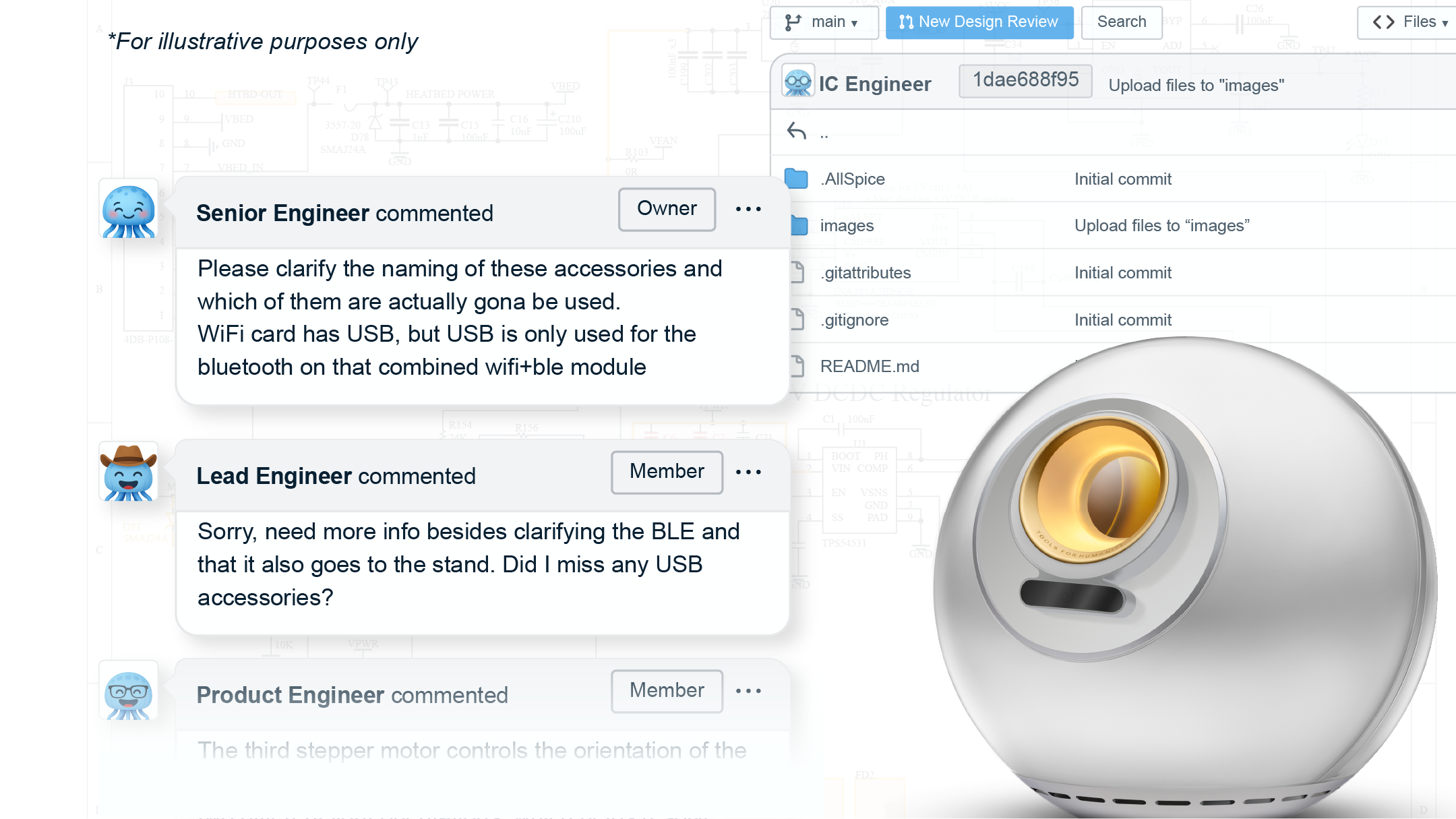
The practical path starts small. Structured design review templates that prompt engineers to record the rationale behind key decisions. Issue trackers linked to specific components or nets, not just to abstract tasks. History and version messages that answer "why" not just "what." Requirement documents stored as structured text alongside the design files rather than as PDFs in a separate folder.
The teams with the best engineers in the world are the ones with the most to gain from capturing that expertise in a form that persists and scales.
Data is the foundation, not the destination
Getting your data into the top-right quadrant is the foundation upon which everything else is built. But it's required, not sufficient. Two things have to follow.
The first is instructions. A raw 50,000-line design file pasted into a prompt won't work. You still need chunking, retrieval, prompt engineering, and tool-use orchestration to deliver the right information to the model in the right form. Data quality sets the ceiling, and how you deliver that data determines whether you get near it.
The second is adoption. The next biggest predictor of AI value, after data quality, is whether engineers actually use it. That comes down to friction. Engineers are busy and deadlines are real. Friction kills adoption, and hardware workflows have plenty of friction already.
This is not a new challenge in hardware. Simulation tools have existed for decades. The technology works and the ROI, for teams that use them well, is substantial. And yet simulation is routinely skipped or abbreviated, because it takes years of experience to configure correctly and interpret confidently. The tool is only as useful as the workflow around it. AI is no different.
For AI to deliver on its promise in hardware, all three pieces need to be in place: data that is complete and structured, instructions that deliver it in the right form, and a workflow that makes using AI the natural choice. Pull any one out and the system falls short.
Data quality is the foundation. Everything else follows from there.


.png)