Pin-to-net mismatches on critical components
One of the most common schematic review issues is also one of the most frustrating: a pin is connected, but not to the right net for the intended function. At a glance, the circuit may look completely reasonable. The symbol is there. The net name looks familiar. The page organization feels clean. Yet somewhere inside a dense block, an enable pin is tied incorrectly, a configuration pin is left in the wrong state, or a microcontroller pin is assigned to the wrong peripheral path.
Why this is easy to miss
These problems hide well because they often look structurally correct.
- Pin names can be long, similar, and easy to skim past.
- Dense symbols make visual checking slower and less reliable.
- Reused blocks can carry assumptions from earlier projects or earlier revisions.
- Reviewers may understand the intended function but still miss a specific pin mapping error.
When teams talk about schematic bugs that “should have been caught,” this category often shows up.
Swapped JTAG connection
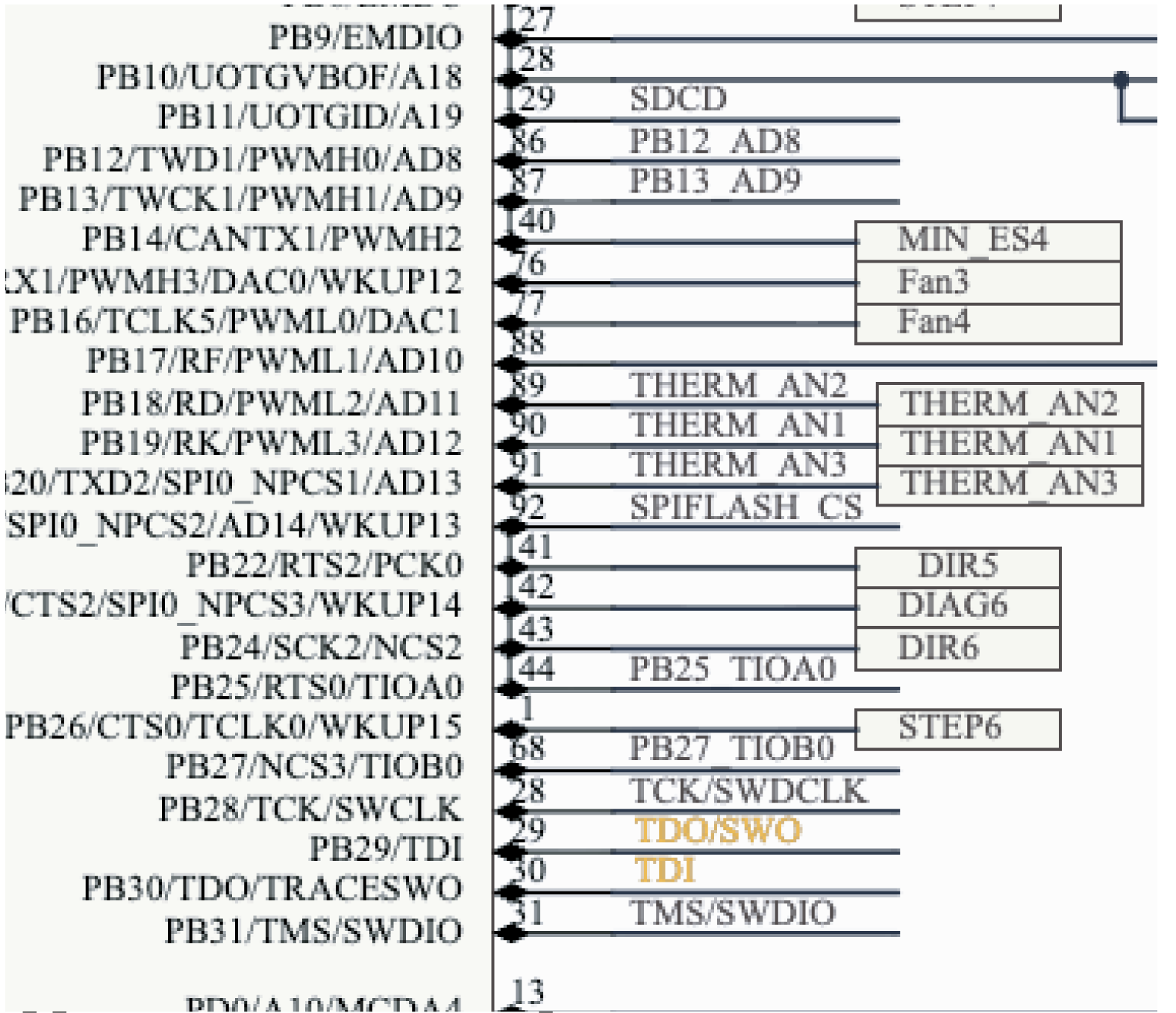
One useful example is a JTAG connection that looks reasonable at a glance, but maps two critical signals to the wrong pins. In one DRCY finding, the system flagged a mismatch on component `U11A`, where the JTAG TDI and TDO signals were swapped between pins 29 and 30. The review noted that pin 29 (`PB29/TDI`) was connected to the `TDO/SWO` net, while pin 30 (`PB30/TDO/TRACESWO`) was connected to the `TDI` net. It then compared those connections against the datasheet context and explained why the mapping was likely incorrect: `PB29` should connect to `TDI`, while `PB30` should connect to `TDO/SWO`.
What makes that finding useful is how clearly it narrows the reviewer’s attention.
- It points to a specific component, pins, and nets instead of forcing an engineer to search manually.
- It explains the likely issue in design terms, not just as a generic warning.
- It ties the finding back to supporting documentation, making validation faster.
- It helps the reviewer understand the likely downstream consequence, in this case broken JTAG debug functionality.
It is also the kind of mistake that can be easy to miss in a rushed review. The schematic may still look clean. The signal names are familiar. Nothing appears obviously broken until someone tries to debug the board later. That is where a first-pass review layer is especially helpful. DRCY can surface the mismatch early, and the engineer can quickly confirm whether it is a real issue before the design moves further downstream. The same pattern also shows up in faster, more constraint-sensitive interfaces.
USB high-speed and full-speed nets tied together
In another DRCY finding, the system flagged `U11B` and showed that the USB high-speed pins and full-speed pins were incorrectly tied together through the `UMCU_P` and `UMCU_N` nets.
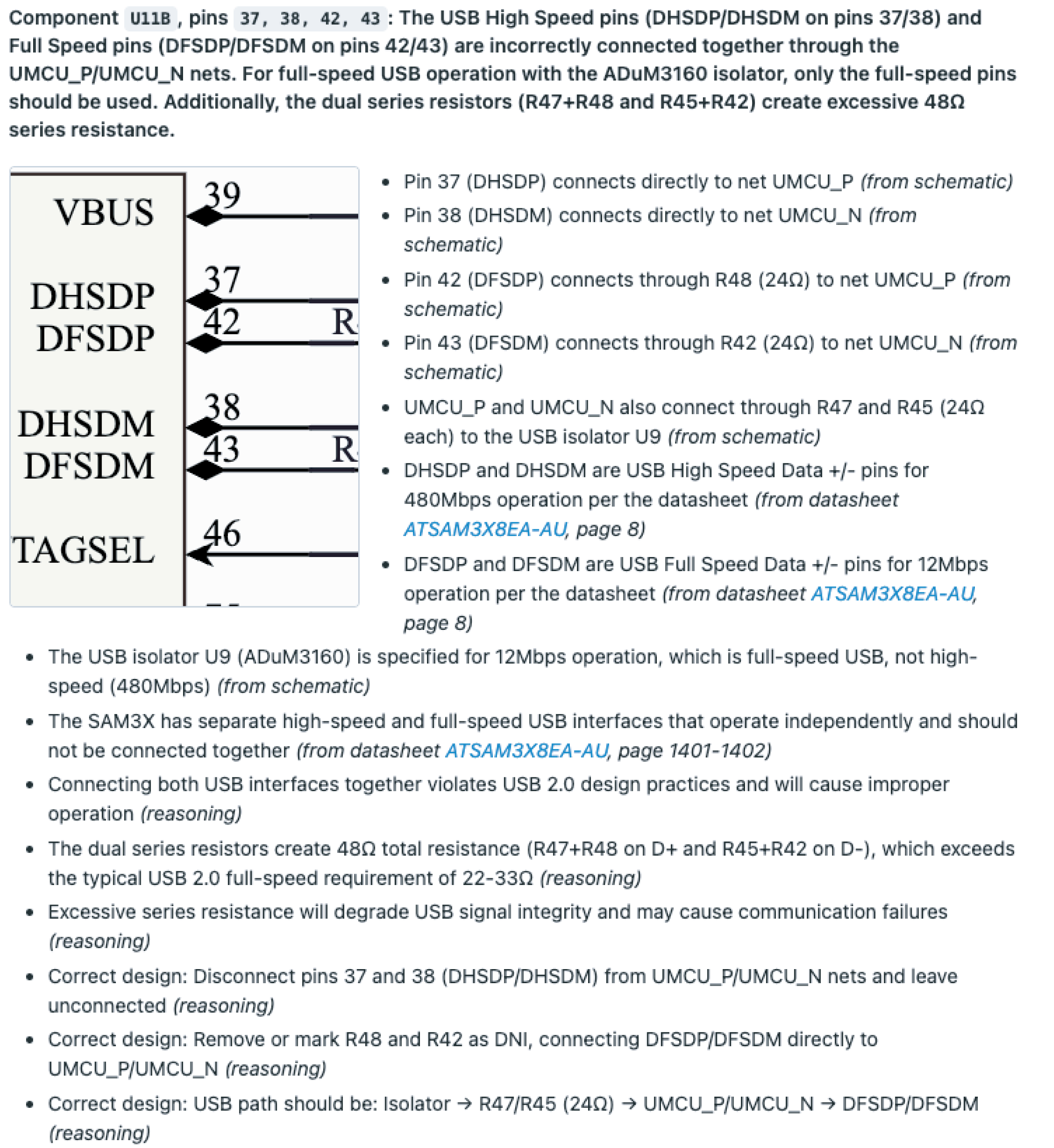
The review then connected that wiring back to the datasheet behavior of the MCU and the ADuM3160 isolator, explaining that the isolator is intended for full-speed USB operation and that the full-speed pins should be used instead.
What makes this example useful is that it shows DRCY reasoning across several layers at once: pin mappings in the schematic, interface roles from the datasheet, and electrical consequences such as excessive total series resistance and degraded USB signal integrity.
That is especially valuable in interfaces like USB, where a connection can look tidy on the page but still violate the intended topology in ways that are easy to miss during manual review.
What the downstream impact looks like
Pin-level mistakes can create hours or days of confusion during validation and bring-up. Symptoms might show up as strange device behavior, configuration failures, missing interfaces, or test results that do not line up with what the schematic appears to promise. By that point, the original issue is no longer a quick review fix. It becomes a debugging exercise.
How AI-assisted schematic reviews help
AI design review tools can inspect component connections at scale, compare expected behavior against context from the design and relevant documentation, and surface connection patterns that deserve a closer look. In Allspice DRCY, that first-pass review happens inside the system of record, using the actual design context available in Allspice. Engineers can then validate the findings, dismiss false positives, and focus their time where it matters most. Connection errors are one obvious source of risk, but they are far from the only one. The next category is just as common and often harder to spot across a large design.