Component validation steps
To demonstrate a recommended process, our team put together a component validation demo that hardware designers can use as a guide. Let’s take a look at a simple example that illustrates the different steps involved:
1. BOM check
The first step in validation is to check component availability. Some companies upload their parts list to online sites like DigiKey, while others send them directly to their contract manufacturers (CMs).
2. Identifying out-of-stock (OOS) components
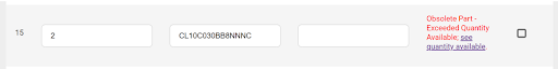
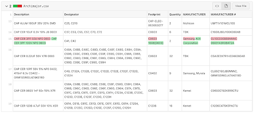
In this (open source) demo project, we have a 3pF ceramic capacitor that is flagged as an end-of-life component.
3. Finding a replacement
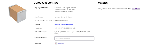
After doing our research, we decide we’ll swap the OOS components for a comparable capacitor.
4. Updating the component library and design
The best practice in this scenario is to update the component in the library and push those downstream to our design so all other designs can use the updated component.

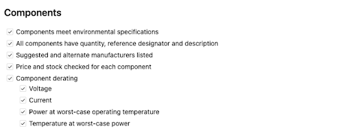
5. Validating component characteristics
Besides having an equivalent capacity, we want to ensure all other parameters, from cost to power, are within specifications. For that, we validate all the items in our design review checklist template that relate to component updates.
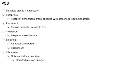
6. Verifying component footprints
Ideally, we want parts that fit the same footprint area. Otherwise, we’d have to update the geometry and communicate the changes to all other affected stakeholders. To ensure we don’t introduce any errors, we make sure to check all the items in the PCB section within our design review checklist template.

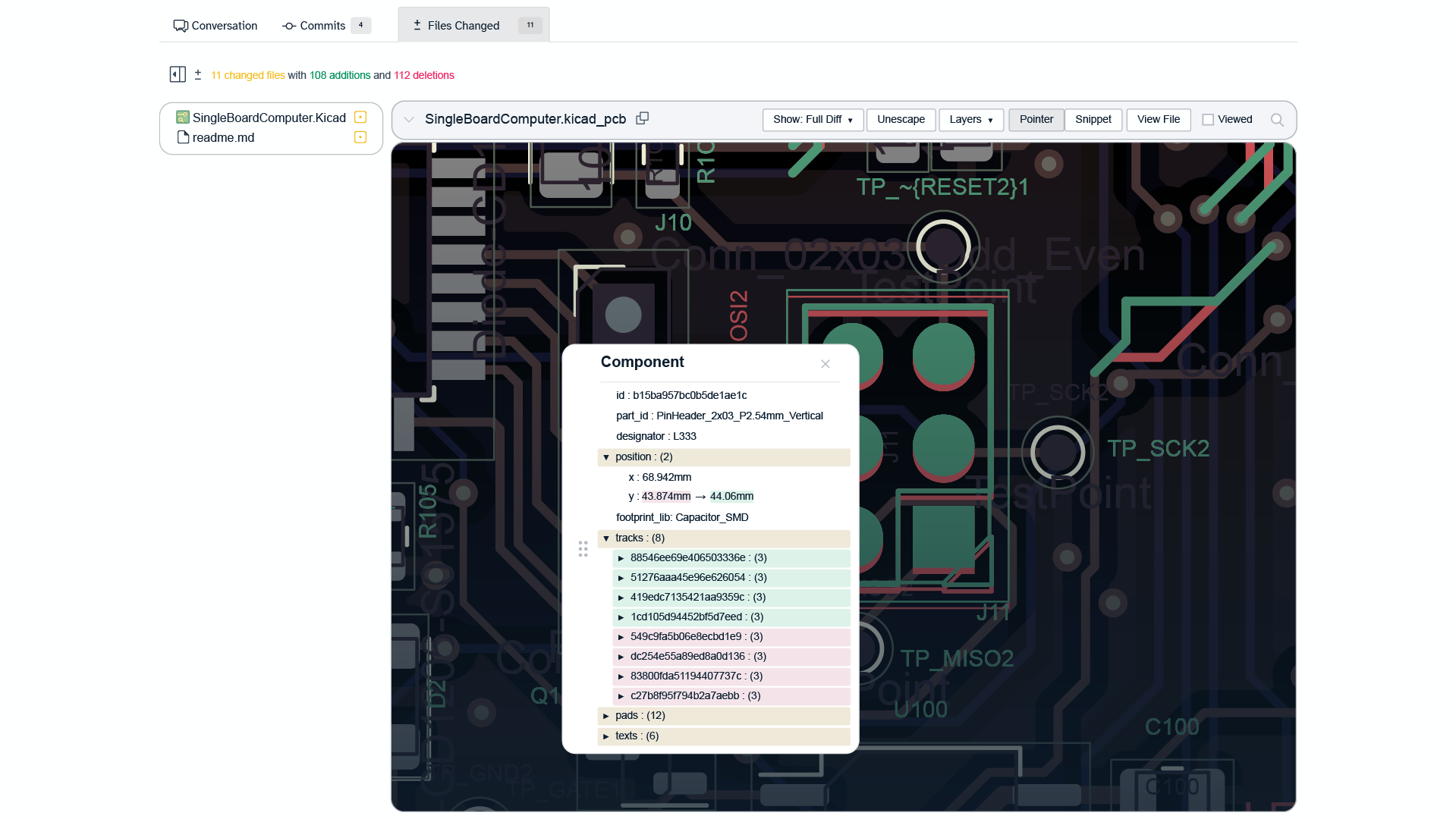
7. Checking for unintended changes
As a sanity check, we take a look at the entire board to scan for unexpected changes. For this demo, our ECAD tool automatically removed a test point in a different area of the board. This happens not to be a big issue for us, but if it was, this is when we would like to find out – rather than after ordering our prototypes.

8. Releasing the updated design
In this demo, we initiated a design review with three goals in mind:
- Collect feedback from peers – that can both catch potential issues by having a set fresh of eyes, and also recommend improvements based on their own experience
- Communicate the updates – letting stakeholders know about the change, either as reviewers or just observers
- Document the changes – for compliance purposes and to help with future troubleshooting

After the review is approved, we can merge, tag and release the updated design.
Links and resources used in this demo
.png)